TEBAOFLEX CABLE ROZ1-K (AS) VFD (EMC) Variable Frequency Drive Cable has been specially designed for Variable Frequency Drive Motors and installations where it is necessary to limit the effects of electromagnetic interference (EMI). This is a flexible cable for fixed installations, for variable speed motors or pumps.
Can’t find what you are looking for? Please E-mail: info@tebaoflexcable.com
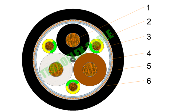
0.6/1kV ROZ1-K (AS) (EMC) VFD Cable
1.Conductor: Copper wires conductor
2. Insulation: XLPE insulation
3. Protective conductor: Copper wire with yellow/green sheath
4. Screen: Aluminum/polyester tape and Tinned copper wire braided shield
5. Sheath: LSZH(ST 8) outer sheath
6. Tear rope
ROZ-K (AS) EMC Variable Frequency Drive (VFD) Cable Construction
| Brand: | TEBAOFLEX CABLE |
| Standards | According to IEC 60502-1 / IEC 60092-353 |
| Type designation: | VFD (EMC) ROZ1-K (AS) |
| Low voltage: | 0,6/1 kV |
| Conductors: | Electrolytic annealed copper, class 5 (flexible), according to EN 60228 and IEC 60228. |
| Protective Conductor: | The ground conductor is divided into three conductors; the equivalent cross-section is approximately 50% of the section of the phase conductor. For 4G cables, ground conductor has the same cross-section as the phase conductors. |
| Insulation: | Cross-linked polyethylene type XLPE according to IEC 60502-1, type HF XLPE 90ºC according to IEC 60092-360. The standard identification of insulated conductors is the following: 3 x +3 G: Grey + Brown + Black + Green/Yellow (3 G) (from 6 mm2 onwards) 4 G: Grey + Brown + Black + Green/Yellow (up to 4 mm2) |
| Assembly of cores: | For 3x+3G cables, the three phase conductors are cabled helically with the three protective conductors distributed in the interstices. For 4G cables, the three phase conductors and protection conductor are cabled helically. |
| Screen: | Aluminium-polyester tape screen helically placed over the insulated conductors. Over the tape there is a tinned copper braid screen. The tape and the braid act as a double screen to cut out all of the electromagnetic interference, with a minimum total section of 10% of the phase conductor, ensuring a total shielding coverage. |
| Outer sheath: | Polyolefin type ST8 according to IEC 60502-1 and type SHF1 according to IEC 60092-360. The ripcord allows you to tear the outer sheath without damaging the screen. |
| Maximum conductor temperature: | 90ºC. |
| Maximum short-circuit temperature: | 250ºC (max. 5 s). |
| Maximum ambient temperature: | 60 ºC. |
| Minimum installation and handling temperature: | 0 °C. |
| Minimum service temperature: | -40ºC (fixed and protected installations). |
| Minimum bending radius during installation: | 10x cable diameter. |
| Impact resistance: | Impact resistance: |
| Water resistance: | AD5 Jets. |
ROZ-K (AS) EMC Variable Frequency Drive (VFD) Cable Installation conditions:
Being very performant cables there are, however, certain precautions that must be taken into account during installation:
– Always respect the bending radius of the cable. Radius below the minimums indicated can cause damage or breakage in the outer sheath.
– Precautions design of the laying. It is necessary that the laying of the cable is done in a careful way, taking care not to damage the outer sheath in irregular areas, sharp edges, etc.
– Fixings/Fastenings. Adapt fastenings so that the cable adopts a natural position in the laying to avoid stress concentration in the outer sheath. Allow a certain degree of freedom of movement in order to absorb possible movements produced by temperature variations. Open Air. Buried. In conduit.
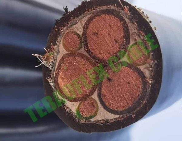
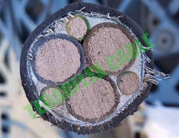
ROZ-K (AS) EMC Variable Frequency Drive (VFD) Cable Parameter
| Cross-section
(mm2) |
Diameter under the braid (mm) |
Outer diameter (mm) |
Weight (Kg/km) |
Open air (A) 1 |
Buried (A) 2 |
Max. R 20°C (Ω/km) |
Voltage drop (V/A · km) 3 |
| 3 x 6 + 3 G 1,5 * | 10,5 | 15,0 | 390 | 63 | 58 | 3,30 | 8,41 |
| 3 x 10 + 3 G 1,5 * | 10,9 | 15,4 | 500 | 86 | 77 | 1,91 | 4,87 |
| 3 x 16 + 3 G 2,5 * | 14,0 | 18,5 | 715 | 115 | 100 | 1,21 | 3,08 |
| 3 x 16 + 3 G 6 | 16,9 | 22,3 | 920 | 115 | 100 | 1,21 | 3,08 |
| 3 x 25 + 3 G 4 * | 16,2 | 21,1 | 1.060 | 149 | 129 | 0,780 | 1,98 |
| 3 x 25 + 3 G 6 | 16,9 | 22,1 | 1.165 | 149 | 129 | 0,780 | 1,98 |
| 3 x 35 + 3 G 6 | 19,2 | 24,5 | 1.475 | 185 | 155 | 0,554 | 1,41 |
| 3 x 50 + 3 G 10 | 22,6 | 28,0 | 2.040 | 225 | 183 | 0,386 | 0,984 |
| 3 x 70 + 3 G 10 * | 26,0 | 30,8 | 2.560 | 289 | 225 | 0,272 | 0,693 |
| 3 x 70 + 3 G 16 | 26,0 | 31,3 | 2.790 | 289 | 225 | 0,272 | 0,693 |
| 3 x 95 + 3 G 16 | 29,3 | 34,7 | 3.420 | 352 | 270 | 0,206 | 0,525 |
| 3 x 120 + 3 G 16 * | 32,8 | 38,6 | 4.205 | 410 | 306 | 0,161 | 0,410 |
| 3 x 120 + 3 G 25 | 32,8 | 39,0 | 4.530 | 410 | 306 | 0,161 | 0,410 |
| 3 x 150 + 3 G 25 | 38,0 | 44,3 | 5.425 | 473 | 343 | 0,129 | 0,328 |
| 3 x 185 + 3 G 35 | 41,5 | 48,2 | 6.655 | 542 | 387 | 0,106 | 0,270 |
| 3 x 240 + 3 G 50 | 48,1 | 55,3 | 8.720 | 641 | 448 | 0,0801 | 0,204 |
| 3 x 300 + 3 G 50 | 53,9 | 61,4 | 10.465 | 741 | 502 | 0,0641 | 0,163 |
| 3 x 400 + 3 G 70 | 63,3 | 71,7 | 14.105 | 886 | 592 | 0,0486 | 0,123 |
| 4 G 1,5 | 6,9 | 11,4 | 185 | 26 | 27 | 13,30 | 33,9 |
| 4 G 2,5 | 7,7 | 12,2 | 230 | 36 | 35 | 7,98 | 20,3 |
| 4 G 4 | 9,2 | 13,7 | 300 | 49 | 46 | 4,95 | 12,6 |
| 4 G 6 | 10,6 | 15,1 | 385 | 63 | 58 | 3,30 | 8,41 |
| 4 G 10 | 12,5 | 17,0 | 555 | 86 | 77 | 1,91 | 4,87 |
| 4 G 16 | 20,8 | 20,8 | 885 | 115 | 100 | 1,21 | 3,08 |
| 1.Reference method F for single-core and method E for multicore cables according to IEC 60364-5-52 in open air at 30°C ambient temperature. 2.Reference method D2 according to IEC 60364-5-52. Directly buried at 0,7 m depth with soil thermal resistivity of 2,5 K·m/W and 20°C of ground temperature. 3.At maximum conductor temperature and cosφ=1. In all cases are supposed a single-phase circuit. |
|||||||
Our Cables Serve Various Industries
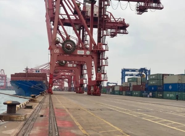
Port
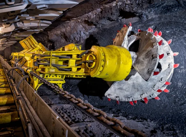
Mining
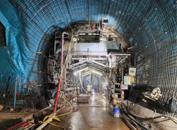
Tunnel
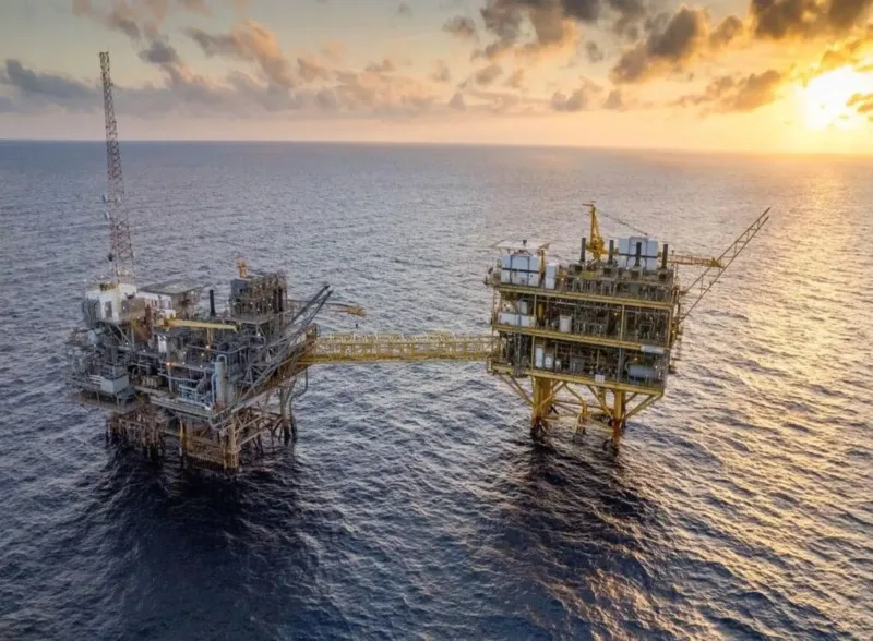
Offshore Platform
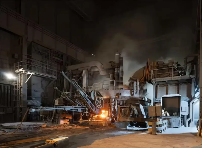
High-Temp Operate
Oil&Gas